• 300 S. Firestone Street, Suite 200-C Gastonia, NC 28052
  • 400 E. King Street, Kings Mountain, NC 28086

Tag Archives: civil engineering

Essential Concrete Strength Testing Methods

Concrete is a critical structural element, and its strength directly impacts a building’s safety. But how do we ensure it meets the demands placed upon it? Concrete strength testing ensures a concrete mix meets design specifications for its intended load-bearing capacity, to ensure the structure’s stability and prevent potential failures.

Concrete strength is most commonly measured by testing its compressive strength, which measures its ability to withstand forces pushing it inwards and together. This article reviews methods for testing concrete strength, both in the controlled environment of a lab and on-site in the field. We’ll also explore preparation methods used for the concrete test specimens and other concrete tests indirectly related to strength.


Q: What units are used when concrete compressive strength is measured?


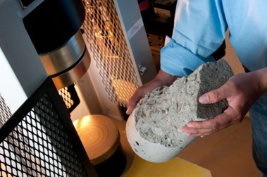
Concrete being strength tested in a lab

Lab Testing: Strength Testing & Related Tests During Planning and Pre-Construction

Lab testing a calculation of concrete strength under controlled conditions. It is typically used for initial mix design and strength evaluation during planning and pre-construction or to help with batching quality control.

Note: While lab samples can be useful, they might not exactly replicate the actual curing conditions on the construction site. Enter the need for field testing for verifying in-situ strength, which will be discussed later in this article.

Lab Concrete Strength Cylinder Test (ASTM C39): This lab test measures a concrete cylinder’s ability to withstand a compressive load until failure and is the primary method used by engineers for determining concrete strength. Cylinders are cast from the fresh concrete mix and cured under controlled temperature and humidity conditions which mimic the actual construction site environment. After a specified period (usually 7 or 28 days), the cylinders are crushed in a hydraulic press. This machine applies a compressive force on the ends of the cylinder, gradually increasing the pressure, until the cylinder cracks or breaks.

The maximum load it can bear is then recorded. The load is divided by the cylinder’s cross-sectional area to obtain the compressive strength. This compressive strength value becomes a benchmark for the concrete’s overall strength.

The desired compressive strength will depend on the intended use for the concrete. Sidewalk and driveway projects, for example, may require a lower psi than commercial buildings and warehouses.

Field cylinders may also undergo the ASTM C39 test (see: Making and Curing Test Specimens (ASTM C31) below for more detail). Field cylinders evaluate the concrete’s actual strength “in-situ” within the structure, while lab cylinders assess the mix design’s potential under controlled conditions.

Unbonded Capping of Concrete Cylinders (ASTM C1231):

In concrete strength testing, unbonded capping is an alternative method for preparing the ends of cylindrical concrete specimens so that they are flat. For an accurate test, the top and bottom faces of the cylinder must be perpendicular to its axis. Uneven load-bearing surfaces can introduce errors in the test results.

Unbonded capping uses a flexible pad, typically neoprene or rubber, instead of a bonded capping material like sulfur mortar or neat cement paste. The pad is placed on each end of the concrete cylinder and steel retainer rings hold the pads securely in place to create a smooth, flat surface.

Unbonded caps are quicker to apply and remove (vs. grinding or cutting uneven ends or bonded capping) for faster preparation of specimens before each test The pads may be reused up to 100 times, reducing waste and cost (vs. single-use bonded caps).

However, unbonded capping cannot be used in every case. ASTM C1231 outlines limitations for using unbonded caps. They are generally not suitable for very low (below 10 MPa or 1500 psi) or very high strength (above 80 MPa or 12000 psi) concrete. Unbonded caps are suitable for concrete with minor imperfections on the ends, up to 5 mm (around 3/16 inches). For larger deviations, grinding or cutting the cylinder ends might be necessary before testing.

Field Testing: Assessing In-Situ Strength

While lab testing provides valuable insights for planning and pre-construction, construction also requires assessing the strength of concrete after it has been poured and cured on-site in actual field conditions. Field testing is key for investigating potential concrete strength issues in existing structures – especially when quick confirmation of adequate strength is needed for construction progress.

Below are a few key strength-related concrete field testing methods and processes:

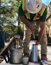
Slump Test (ASTM C143): The Slump Test is a quick test that measures the consistency and workability of fresh (unhardened) cement concrete, which impacts its compaction and ultimately, its strength. Concrete with a higher slump may be easier to place but can lead to trapped air and reduced strength. The Slump Test is a valuable tool for concrete quality control in the field, ensuring the correct consistency (not too wet or too dry) and cohesion (the ingredients are holding together well).

To conduct the Slump Test, a cone-shaped mold is filled with concrete in layers and rodded to remove air bubbles. The mold is lifted straight up, and the slump is the distance that the center of the concrete settles. This indicates how easily the concrete will flow and fill forms, with a moderate slump (between 1/2 inch and 9 inches) being ideal for most applications.

Sampling of Freshly Mixed Concrete (ASTM C172): Obtaining a representative sample of fresh concrete ensures accurate concrete strength testing. Following ASTM C172 ensures a well-mixed composite sample that accurately reflects the overall properties of the concrete batch for reliable strength testing. Samples are taken from the middle portion of the concrete batch, avoiding the first and last portions that may not be well mixed.

For portable drum mixers and mixer trucks, sampling occurs during discharge, when a container is inserted into the stream, or the concrete flow is diverted into a container during discharge. For paving mixers, samples are collected from five locations after the entire contents of the paving mixer are discharged onto the ground where the concrete will be placed.

Regardless of the mixer type, it’s crucial to collect the sample within the specified timeframe (usually 15 minutes after obtaining the first portion) to ensure the properties haven’t changed significantly.

Making and Curing Test Specimens (ASTM C31): ASTM C31 outlines the process for making and curing cylindrical or beam-shaped concrete test specimens in the field. Fresh concrete is obtained following ASTM C172 and placed in molds in layers. Each layer is rodded to eliminate air bubbles, and the top is smoothed. The molds are covered to prevent moisture loss and kept at a specific temperature range for an initial curing period. Then, the specimens are demolded and submerged in water or a limewater solution for final curing until testing, typically at 28 days. This ensures the concrete reaches a controlled and standardized strength for accurate compressive strength test results.

Temperature of Concrete (ASTM C1064): ASTM C1064 is a standard test method for determining the temperature of freshly mixed concrete at the time of placement. It outlines how to measure the temperature using a specific type of thermometer that can be inserted into the concrete. The field concrete test ensures the concrete is within a proper temperature range (typically between 30°F and 120°F or 0°C and 50°C). This is important for concrete strength because extreme temperatures can affect the setting time, workability, and thus, the ultimate strength of the concrete.

Unit Weight (ASTM C138): ASTM C138 is a test method to determine the unit weight (also sometimes referred to as density) of fresh concrete. Unit weight is important for estimating yield of concrete from a mix design (knowing the unit weight allows engineers to calculate the actual volume of the resulting concrete from the ingredients) and quality control (unit weight variations can indicate potential issues with the mix proportions, mixing process or presence of air bubbles).

The test involves filling a specific mold with the fresh concrete and compacting it according to the standard. The weight of the filled mold is then measured, and dividing this weight by the known volume of the mold gives the unit weight of the concrete.

This test has an indirect relationship to concrete strength. Higher unit weight typically indicates a denser concrete mix with fewer air pockets, which usually means a higher strength. However, it’s not a standalone measure of strength. For example, a concrete mix with a higher unit weight due to the amount of heavy aggregate might not necessarily be stronger than a mix with a lower unit weight that has a more optional mix design.

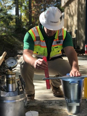
Air Content by  Pressure Method (ASTM C231): The Air Content by Pressure Method test measures the volume of air entrapped within the concrete mix and is used for concrete made with relatively dense aggregate particles, excluding internal air voids within the aggregates themselves. The pressure method test uses a special apparatus called an air meter, which is filled with a concrete sample and water. The air meter bucket rim is cleaned and the top section is placed, after which sealed water is introduced through one of either petcocks until all air bubbles dissipate, then the petcocks are closed. Air pressure is applied, and the change in volume of the trapped air is measured. Maintaining the desired air content is crucial for ensuring concrete durability, workability, and achieving the target strength. Too little air can lead to freeze-thaw damage, while too much air can reduce strength.

Air Content by Volumetric Method (ASTM C173): The Air Content by  Volumetric Method outlined in ASTM C173 is a test to measure the air trapped within fresh concrete. This test helps ensure the concrete has the proper amount of air for workability and freeze-thaw resistance. Its value lies in its ability to accurately measure air content in concrete where the air content by pressure method might struggle, such as lightweight concrete and those with highly porous aggregates. Generally, higher air content leads to lower strength, however it is not a direct measure of concrete strength.

For this test, concrete is placed in the meter bucket in two layers, rodded and sides tapped for each layer. The bucket rim is cleaned, and the graduated neck is placed on the bucket and clamped for a tight seal. The funnel is then placed in the neck and a small amount of water is added before introducing 2 pt of 70% isopropyl alcohol, then the remaining water is added up to the 0 mark. Then the top is added and sealed into place.

The meter is then shaken and rolled to release air bubbles. The water level in the neck rises due to the displaced air, and this change in level indicates the air content as a percentage of the total concrete volume. This test helps ensure the concrete has the proper amount of air for workability and freeze-thaw resistance.

Ready to begin testing?

By employing a combination of these tests, engineers gain a comprehensive understanding of concrete’s properties, ensuring a safe and structurally sound construction project. Need concrete strength testing services or other concrete construction materials testing?  Contact The Thrasher Group NC about our AASHTO and CCRL accredited test lab and services.


Case Study: Smart Water System Project Management Creates Funding for City Infrastructure Plan

The Thrasher Group North Carolina Completes City Water System Replacement Project Under Budget, Funding Forward-Thinking 5-Year Water Infrastructure Plan

Project Overview:

High Shoals, NC Water System Replacement (Phase 1)
The City of High Shoals’ public water supply infrastructure included thousands of feet of water line at or nearing end of life. The water system was experiencing frequent breaks and losing water each day. To prevent increased maintenance costs and potential interruptions to service, the city needed a plan to replace the water line.

The City of High Shoals hired The Thrasher Group North Carolina to design and replace the water system. The project was funded by a Community Development Block Grant (CDBG) grant from the North Carolina Department of Commerce.

Water System Replacement

Project Goals

  • Replace the largest water line segment in the City (5,980 linear feet)
  • Replace faulty meters, 73 meters hooked directly into the line
  • Reduce water loss (thousands of gallons per day)
  • Ensure cutover to new water line with minimal disruption to water service
  • Work with local grant writer to secure Community Development Block Grant
  • Meet all applicable North Carolina state regulations

Civil Engineering & Surveying Services Provided

  • Design Surveys
  • Design
  • Plans & Specifications
  • Permitting Coordination
  • Contract Documents
  • Bidding Services
  • Construction Administration
  • Right-of-Way/Easement Acquisition Surveying & Mapping
  • Final Project Certification

Project Approach
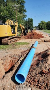
The Thrasher Group North Carolina took a phased approach to the water line replacement needed in High Shoals. This case study focuses on the first Phase of the project, which involved replacing the largest water line segment in the city (over 3,000 feet of 12 inch water line, around 1,000 feet of 8 inch water line and 1,500 feet of 6 inch water line). 

The second phase of the project will involve replacing the remaining water lines in town and The City of High Shoals, NC, is currently in the application process for another grant for Phase 2 of the project.

Project Challenges
One of the main challenges of the project was that the new water system replacement needed to be installed without disrupting water services to the residents. The Thrasher Group would need to work closely with the City of High Shoals to develop a phased plan that would minimize downtime to the community’s water services.

Another challenge of the project was that each phase or section of the new water line had to be disinfected and pressure tested before residences could be connected. This process took several weeks to complete and required Engineer inspections and NC State approval.

Project Outcomes
The project was a success, completed on time and under budget.

  • Minimal Downtime – Leveraging jumpers installed at key locations through the project, The Thrasher Group North Carolina successfully replaced the main feeder lines while keeping water service active, with minimal disruption to services for local residents and institutions.
  • Completed On Time – The Thrasher Group successfully managed the water system replacement construction timeline and key milestones like Engineer inspections and NC State approval. The project was completed on time.
  • Completed Under Budget – Because the project was completed under budget, the Division of Water Infrastructure (DWI) permitted the City of High Shoals to use some of the remaining grant funds to pay for updating the City’s Asset Management Plan.  Thrasher was able to update the Asset Management Plan and Capital Improvement Plan that they had originally prepared for the City.  This updated inventory of all water and sewer assets by condition and age will position High Shoals to proactively build out its water infrastructure, preventing future water loss and service disruptions.

Client Quote
“The Thrasher Group North Carolina did an excellent job on this project. They were very professional and worked closely with us to minimize interruption to water service for our community during the replacement.”
P.J. Rathbone, High Shoals, NC, Mayor


North Carolina’s Water Infrastructure Challenges

Growing communities across North Carolina continue to face water infrastructure challenges in meeting their water and sewer needs, leading to moratoriums on new site development, water shortages and sewer overflows.

In fact, in the past 20 years, over 30 North Carolina communities  have had a moratorium on new development due to water or sewer capacity constraints.

The North Carolina Department of Environmental Quality (DEQ) is working to address water services challenges through various programs, such as The Clean Water State Revolving Fund. This initiative provides low-interest loans to communities for wastewater infrastructure projects.

While these initiatives have decreased the number of moratoriums in recent years, it is still essential for North Carolina communities experiencing rapid growth to proactively seek assistance from professional resources like water systems engineering firms.

Civil engineering firms with a background in water system planning can play a pivotal role in auditing existing water inventory and ultimately creating and implementing comprehensive 20-year infrastructure plans.  This article explores 5 ways professional water systems engineers can help growing populations to meet their current and future water needs.

1. Water Systems Inventory Assessment

The first step in preparing water and sewer systems is a comprehensive assessment of the existing water supply system. A water systems engineering firm has the resources to conduct thorough audits of existing water system inventory, evaluating the count/length, condition, capacity, and performance of waterlines, taps, hydrants, manholes, treatment plants, pump stations, storage facilities, distribution networks and more. The assessment may also break down inventory as residential, commercial and industrial.

This assessment serves as the foundation for informed decision-making. It may include recommendations for:

  • Immediate repairs
  • Ongoing maintenance with suggested cadence
  • Immediate upfits and 20-year infrastructure upgrade plan

In some cases the assessment may also recommend that the community focus on community water use awareness, in cases where water conservation practices could easily reduce strain on the existing infrastructure.

2. Water Systems Inventory Management

An initial inventory assessment is needed, but ongoing inventory management is crucial for future success. Inventory management ensures the continued smooth operation of water and sewer systems.

Civil engineering firms utilize advanced techniques, such as Geographic Information Systems (GIS), to create detailed inventories of assets. This includes waterline, pipes, pumps, valves, meters, and treatment facilities, and their current condition (i.e. the waterline may be aging in certain locations and likely to fail if not replaced). GIS can also be used to model the flow of water through pipes and waterlines. This information can be used to identify areas where there is a risk of water pressure problems or contamination.

Accurate inventories enable efficient maintenance, timely replacements, and strategic water system planning, preventing unexpected water infrastructure failures.

3. Demand Projections and Capacity Planning

Professional water systems engineering resources can work with communities to analyze population growth and water use patterns to forecast water and sewer demands. Our water and sewer engineers recommend the creation of a 20-year plan to ensure that infrastructure upgrades keep pace with growth.

Water systems engineers can assess the current system’s capacity and identify areas for enhancements to meet future population demands on the water infrastructure. Engineers use this data to upfit water systems to accommodate current requirements and design water infrastructure expansion plans, ensuring longevity and preventing failure.

In addition to water systems planning, most engineering firms offer end-to-end services, including the design and implementation of water services projects, along with construction monitoring and oversight services –  ensuring the project is completed correctly, on time and within budget.

4. Innovative Solutions and Water Systems Modeling

Civil engineering firms can bring innovative solutions to the table. This may include the implementation of smart technologies for real-time remote monitoring via sensors installed on water systems assets (e.g. leak detection systems) or the integration of renewable energy sources for sustainable operations.

Civil engineers can leverage water systems modeling software to simulate the performance of water systems under different conditions. These models can then be used to identify potential design problems and risk of operational failures before they occur.

5. Environmental Impact Assessment:

Growing communities must balance development needs with environmental conservation. Civil engineering firms conduct comprehensive environmental impact assessments, ensuring that any expansions or new infrastructure projects meet regulatory standards and minimize ecological disruption. This proactive approach fosters environmental sustainability.

In some cases, civil engineers will help communities to implement water conservation and reuse programs to reduce demand on the water system. This includes developing and implementing water use restrictions, public education campaigns, and water-efficient technologies.

6. Community Engagement and Compliance

Civil engineering firms actively engage with the community stakeholders. By fostering open communication, they address concerns, gather feedback, and incorporate community needs into the design and planning processes.

Additionally, civil engineers ensure that all plans adhere to local, state, and federal regulations, guaranteeing compliance. Water systems engineers can also help with generating reports needed for regulatory bodies and stakeholders on water quality, usage and system performance.

Does your growing community need water systems engineering help?

The Thrasher Group North Carolina is proud to support communities with consulting engineering and field services including survey, materials testing and construction management. To talk to one of our team members about your community’s water services needs, fill out our contact form or give us a call at 704-864-2201.


A History of Successful Projects and Repeat Clientele

Our company history goes back to 1983, when H. Wood “Woody” Thrasher, PE, a young engineer with an entrepreneurial spirit, started a civil engineering firm with his father, a seasoned engineer himself. Their philosophy was centered around the commitment to building business through successful projects and the idea that strong relationships lead to repeat clientele.

Since that time, The Thrasher Group – a multi-disciplinary firm composed of professionals in civil engineering, architecture, landscape architecture, environmental, and field services – has been growing throughout Appalachia and the Mid-Atlantic region.

Woody operates The Thrasher Group North Carolina – a separate company with roots that go back to 1964 as Robinson & Sawyer – under the same principles. Our team is dedicated to improving communities where we live and work right here in the western Piedmont region and across the border in upstate South Carolina. We bring talented, home-grown professionals together in a collaborative environment and give them opportunities to do meaningful work on projects that matter to local residents.

By listening to our clients and prioritizing their needs, we are able to find strategies and solutions that continue to produce successful projects and strong relationships.


Read about the Gastonia office location’s ties to local history: